Preparing models
Model requirements
Understand which parts are compatible with 2.5-axis CNC and DXF Exporter, and which are excluded automatically.
DXF Exporter is for parts modelled as if they are made from sheet material — CNC routing, laser cutting, plasma cutting, and similar processes where stock starts flat and features are cut into one or both faces. It is not a full CAM system for arbitrary 3D toolpaths.
Imported and native Onshape geometry are validated the same way. You do not need a perfect model before running validation; validation is there to show what needs attention before generation or download. See Validation warnings for what each status means, and DXF Export Prep for overcam, ball-cut edges, or marking parts to exclude.
Sheet-like parts
A compatible part reads as machined sheet stock. Validation looks for:
- A planar bottom face (the back face) it can identify as the stock underside.
- A top face parallel to that bottom at the part thickness.
- Features that map to supported toolpath types — outside and inside profiles, pockets, holes, V-cuts, ball-cuts, and similar layered geometry.
If any face cannot be classified into a supported toolpath type, the part is treated as incompatible with 2.5-axis export.
Compatible parts are organised in the download package by material and thickness. See Materials and thicknesses for how that works.
Onshape sheet metal parts are supported as well. The export uses the unfolded body, not the folded 3D shape. See Sheet metal flat pattern exports.
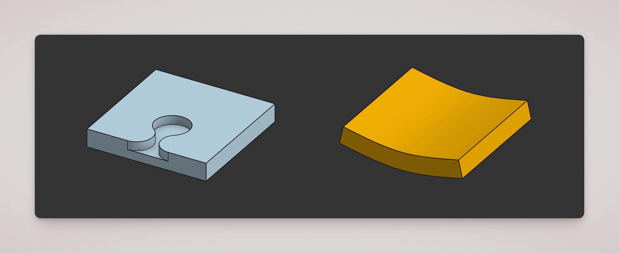
Left: a sheet-like milled part with a pocket. Right: a bent solid that is not a sheet metal flat pattern and is incompatible with 2.5-axis export.
Geometry that fails validation
If validation marks a part as incompatible, check whether any of these apply:
- No planar back face — for example, a part whose largest underside is cylindrical rather than flat stock.
- No front face aligned with the back — validation cannot establish a consistent sheet thickness and machining direction.
- Faces at unsupported angles — every face must be parallel or perpendicular to the stock faces, unless it is a recognised cut type (see below).
- Unrecognised curved or freeform surfaces — surfaces that are not classifiable as a V-cut or ball-cut.
- V-cuts that do not open to a horizontal surface, or whose deepest edge is not level across the groove.
- Ball-cut features where the expected toolpath edge is missing, not level, or adjacent plunge faces are not parallel or perpendicular to the stock.
- Holes that are not simple through-cuts — the hole axis should be perpendicular to the stock faces, with planar end caps. Curved walls, conical ends, or blends may be treated as incompatible.
Double-sided milling
A part is flagged for double-sided milling when material is machined from both faces of the sheet — features on the top and bottom, not only from one side. The part may still pass the general 2.5-axis geometry check, but DXF export is not supported for double-sided parts today.
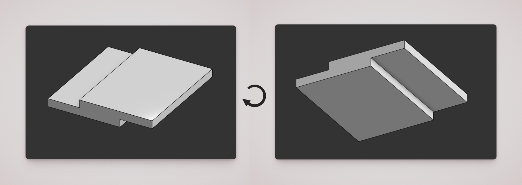
If you see this status, review whether both sides truly need machining. Common approaches include splitting the design into two single-sided parts, or remodelling so all cut features sit on one face.
Parts excluded from validation and export
Some parts never enter the validation table or the downloaded package. At the moment, that includes:
- Composite parts — Onshape composite bodies are skipped automatically.
- Parts marked excluded in DXF Export Prep — bodies tagged with the prep custom feature’s exclude option.
- Suppressed assembly instances — parts suppressed in the assembly tree (assemblies only).
Excluded parts are listed separately in the app with a reason. They are not the same as incompatible parts, which are validated but cannot be exported as 2.5-axis DXF.
To mark a part for exclusion yourself, use DXF Export Prep.