Preparing models
Ball-cut edges
Rounded grooves machined with a ball or bull-nose cutter — and the edge DXF Exporter needs at the deepest point of each groove.
Ball-cut toolpaths use a ball or bull-nose cutter to machine rounded grooves along the stock face. They are common for channels and similar features, such as the finger recess on the back of a door handle. This is not the same as a bullnosed edge, where a profiling or grooving bit rounds an outer edge of the part. Ball-cut geometry is the recess in the face; bullnose edge geometry is a rounded outer edge.
You model the ball-cut face in the Part Studio. For DXF Exporter to include that toolpath, the model also needs an edge at the deepest point of each groove — the path the cutter follows. That edge is easy to omit when modelling the groove in Onshape, so validation flags parts where it is missing.
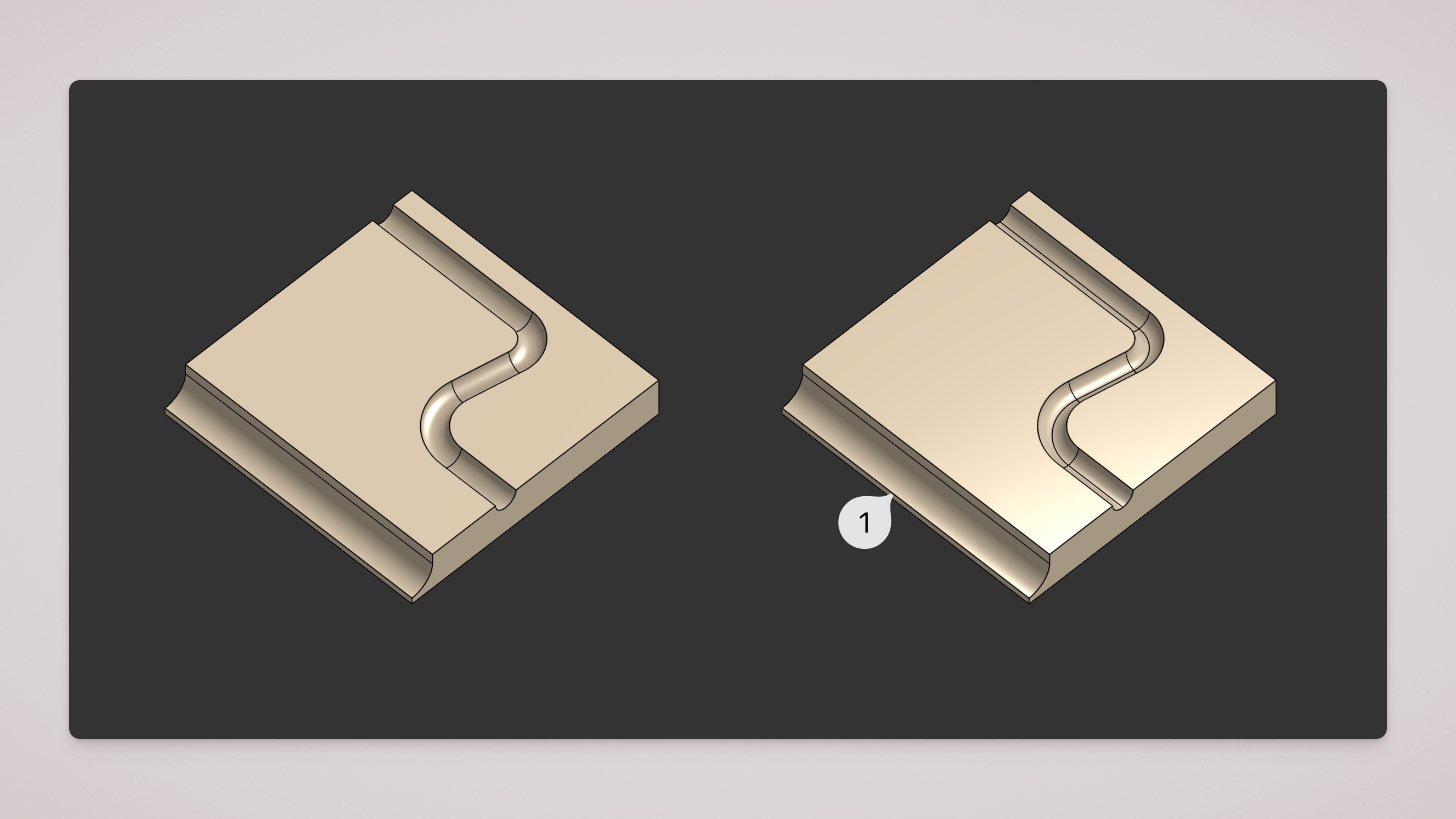
Left: No toolpath edge at the deepest point. Right: DXF Export Prep creates the missing edges. 1: a boundary groove where the deepest point is already a part edge; the exporter can use this without prep.
Adding ball-cut edges with DXF Export Prep
Validation will warn with Ball-cut path missing when a part has ball-cut geometry but no toolpath edge at the deepest point of the groove. If you see that warning, add the prep feature (or review why the geometry was flagged). See Validation warnings.
Use the DXF Export Prep custom feature to add missing ball-cut toolpath edges. The feature finds eligible ball-cut faces and splits them at the deepest plane of each groove, creating the edge the exporter expects. Insert the feature in the Part Studio and enable ball-cut edges for the parts that need them.
Use the DXF preview to check that ball-cut paths appear on the expected layer. See DXF layers and toolpath types for how ball-cut toolpaths are named and coloured.