Validation & fixes
DXF Material Prep custom feature
Install and use DXF Material Prep to control grain direction and review front/back orientation before DXF export.
DXF Material Prep is a companion Onshape custom feature. DXF Exporter handles validation and export; Material Prep records grain direction and which face is treated as the back in the Part Studio. For overcam, ball-cut edges, and exclusions, use DXF Export Prep.
Install the custom feature
Open DXF Material Prep in Onshape and add the feature to your toolbar, then insert it into the Part Studio feature list like any other custom feature.
If you have not used custom features before, Onshape's guide to adding custom features covers adding one to the toolbar.
When to use it
You can validate first and use Material Prep to resolve orientation or set grain after the validation table shows what needs attention, or prep up front if you already know the stock direction and face, then validate to confirm. Revalidate after changing Material Prep inputs.
What Material Prep can do
| Action | When you need it |
|---|---|
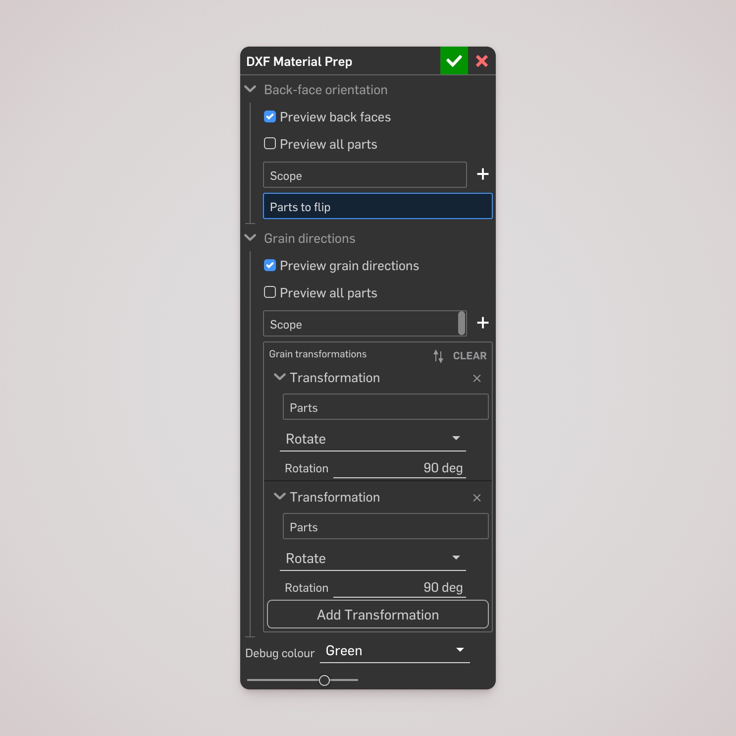
| Preview back faces | Highlight the effective back face (face down on the machine bed) so face-wrong panels are easier to spot. |
| Flip parts | Swap front and back for eligible through-cut planar parts — clears the ambiguous orientation warning for those parts. |
| Preview grain directions | Show the effective grain direction inferred by DXF Exporter, including on corresponding folded sheet-metal faces. |
| Rotate grain | Rotate the inferred grain direction by a chosen angle for one or more parts. |
| Set grain from a mate connector | Use a mate connector's X axis as the required grain direction. |
Preview controls can cover every part or an include/exclude scope. Previews are temporary editing aids — turn them off after review to keep regeneration fast.
Review and flip orientation
The back face is the face that lies down on the machine bed. When stock has a preferred face (veneer, coating, grain), that orientation matters. For what the ambiguous orientation warning means, and when to suppress it with symmetric finish instead of flipping, see that guide.
- Enable Preview back faces and check the highlighted faces.
- Add any face-wrong eligible bodies to Parts to flip.
- Rebuild the feature and revalidate in DXF Exporter.
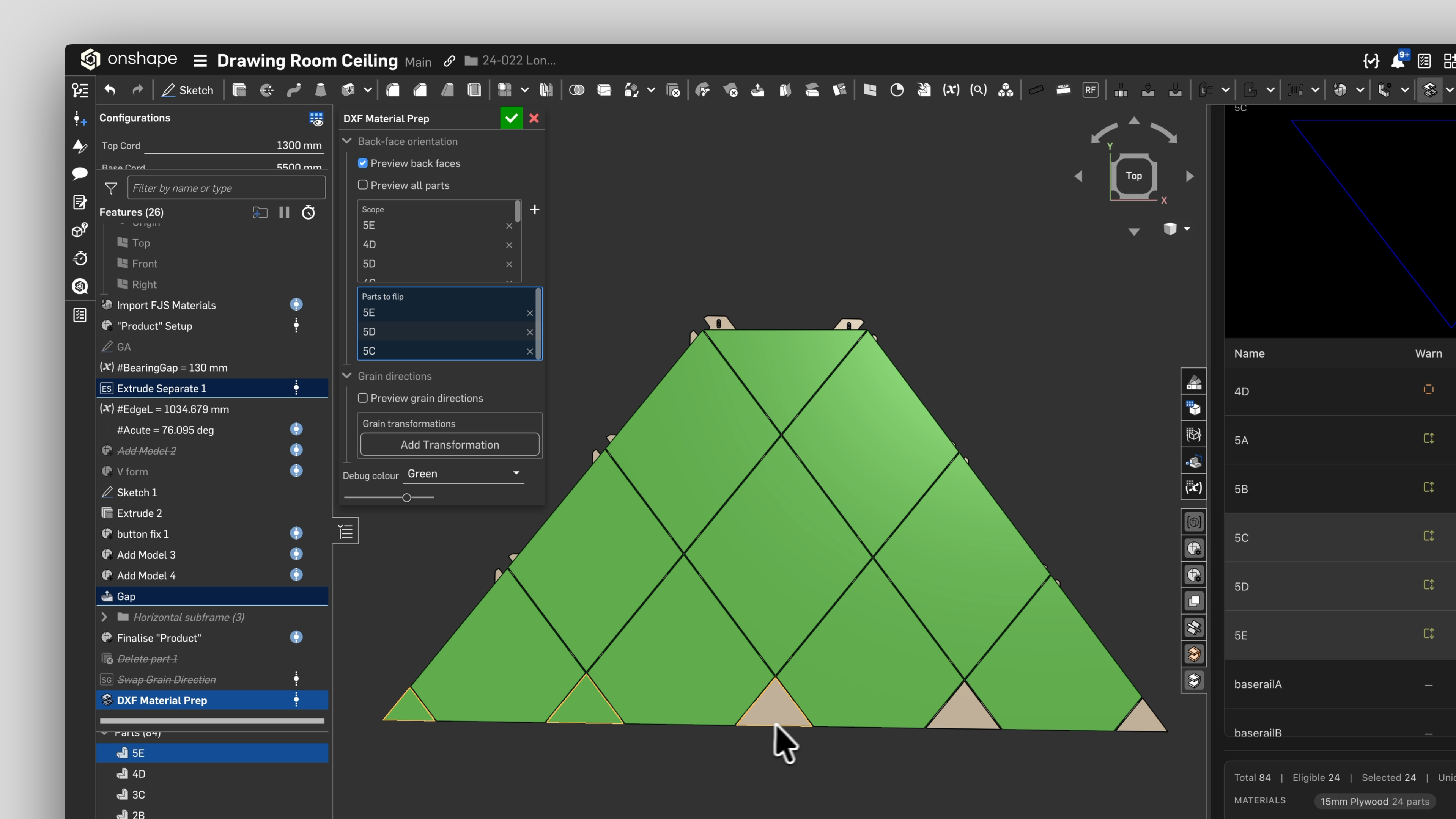
Flipping is limited to through-cut planar parts. Parts with pockets or stepped faces cannot be flipped because their machined face already determines orientation. For active sheet metal, select the folded body.
Set grain direction
DXF Exporter infers an initial direction from each planar part. Add items to Grain transformations when that direction does not match the stock:
- Rotate — angular offset. A 90° rotation is useful when grain should follow the other principal part axis.
- Mate — uses a mate connector's X axis. That X axis must be parallel to the selected back-face plane.
Use Preview grain directions while editing to confirm the effective result. For sheet metal, the preview appears on a corresponding folded back face. A mate-based direction requires a planar face; use Rotate for curved-only sheet-metal panels.
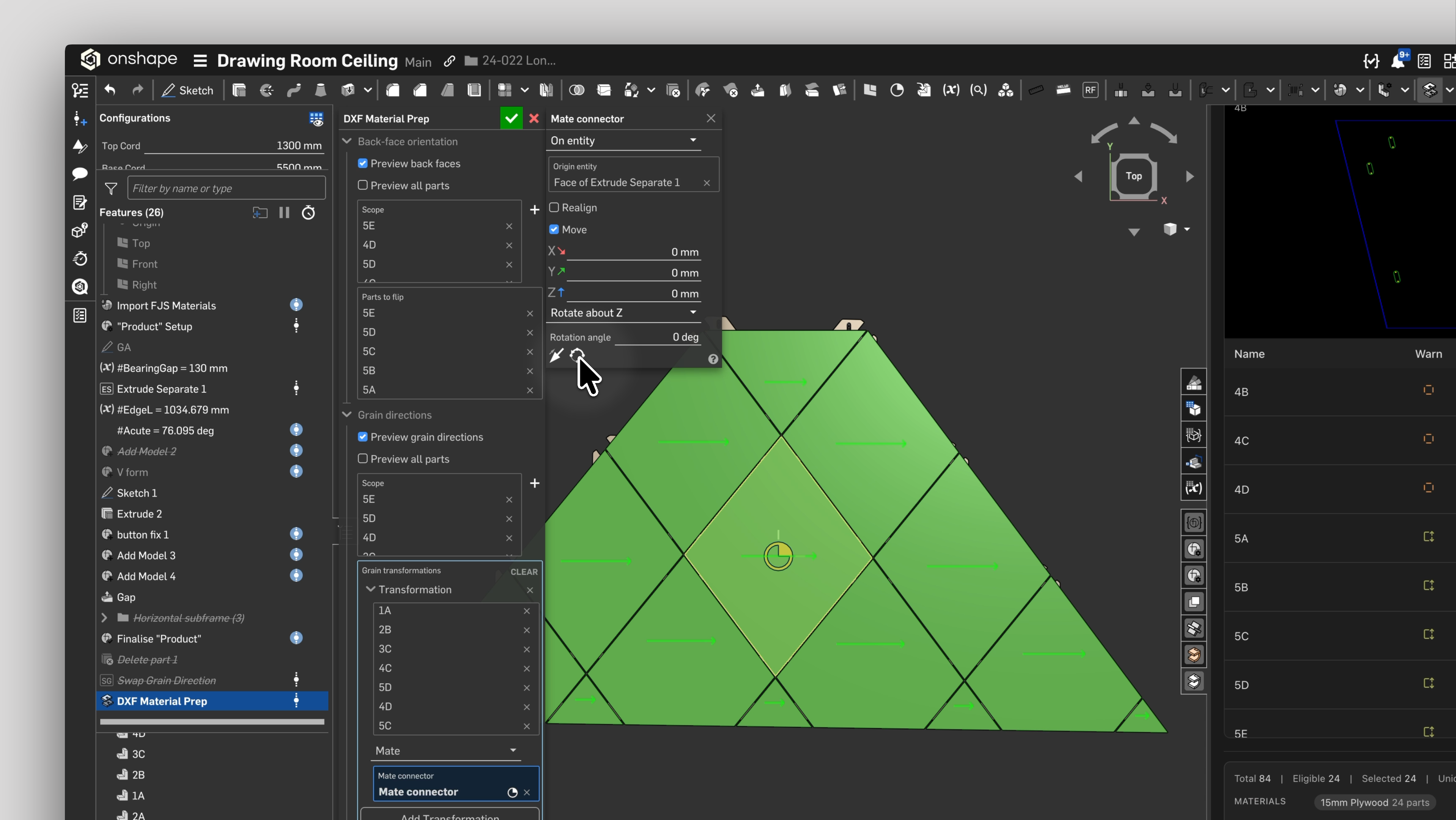
Grain direction controls DXF orientation for nesting and downstream CAM. Review the generated preview before machining.
After material prep
Run validation again. A flipped part no longer flags an ambiguous-orientation warning, and generated DXFs use the effective grain direction when choosing their rotation. See Validation warnings for any remaining statuses.